Monday, May 16, 2011

Franzinator Part II

I have completed the Franzinator air dryer/water separator.  This was a lot of fun to build and seems to work, though I have yet to seriously measure the results.  The previous post describes the workings, so here are the final pictures and a few notes.

This shows the Franzinator and his neighbor the Swinging Lumber Rack.  I've insulated the vessel and the water supply and return lines.  The water line is coiled around the vessel inside the insulation.  I need to disassemble the whole thing and solder the copper coil to the vessel, now that I know it all works.
Here is a little improvement--the air bleed valve that allows the compressor to start without pressure on the head was leaking down the tank over a period of about 24 hours.  In order to hold the air better, I added a ball valve so at the end of the day I can shut off the bleed valve.  All the power to the shop is on a disconnect so no machinery is powered unless I am there to turn it on (to keep the 5 year old boy's future texting abilities intact).  I Just have to remember to open it when I start the compressor again.
Here is the little pump head.  This was a great find at the surplus store.  I got this unit, another larger pump (for the shop air conditioning project forthcoming), a linear actuator (don't know where that fits in, but I see mucho possibilities), and four gas springs (which are very hard to find at a reasonable price--for my adjustable roller table--another story) for 40 bucks.
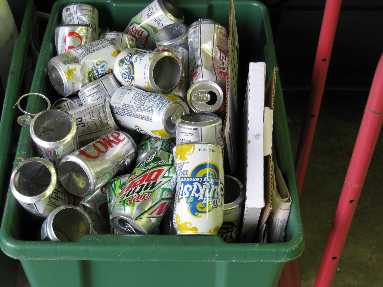
Here is proof that the aluminum cans I used to make the cooling fins for the air intake line were not all beer cans.
Here are the cooling fins during installation.

A closer look.  I drilled a 7/8" hole in the bottom of an aluminum can, then cut the bottom off with the band saw.  I split the ring with tin snips to allow it to fit around the air line.  In order to get a more snug fit, I used this special made tool to crimp the interior of the ring, thereby making the circumference smaller.
Here is the special tool.  I made this to crimp the tang on fretwire during the Yoda rebuild.  It is a cheap pair of lineman's pliers with a groove and tang milled into the jaws and the lower jaws milled out to allow the pliers to close far enough for the tang and groove to engage
Here is the whole shebang assembled.  Note the wall switch above the water cooler.  I initially had the pump wired to the compressor motor starter to come on whenever the compressor came on.  But I decided that I needed more circulation time to cool the vessel, so I put the pump on its own switch so I can pre-cool before I need dry air.  The water cooler is wired hot all the time, so it is thermostatically controlled making 45 degree water per its original design.  But the main disconnect does disengage it so during long periods (weekdays) away from the shop, I'm not wasting electricity.

In a crude test using my voltmeter to measure temperatures, I got the following:
Ambient: 69 degrees
Humidity: uncomfortable
Air Line from Compressor into vessel after 10 minute run time: 195 degrees
Air Line from vessel into air tank: 150 degrees
Water pump head after run up: 55 degrees
Water drained from vessel: not measured, but looked to be about 25ml (a guestimate based on my memory from junior high science of what a 50ml graduated cylinder looks like).

So, if my "data" is any indication, I am on the right track.  I plan to take more scientific measurements in the future, perhaps a before and after when I re-coil the cooling coil after I clean the vessel and solder the coil in place to get proper conduction.

Friday, May 6, 2011

Mr. Compressor Meets "The Franzinator"

 Recently I became the caretaker of a cute little plasma cutter.  I have been wanting one of these for some time and was excited to foster its care while its owner re-arranged his shop situation.  I immediately hooked it up and started playing around, cutting steel letters with very poor results.  Knowing from research that this was not what I should expect, I began to delve into the "whys".  Not unlike my miserable success with spraying finishes, much had to do with lack of any experience, so I expect that perseverance will eventually pay.

Upon talking to the plasma cutter's owner, I learned that the consumables are probably in need of replacement, so I undertook acquiring those supplies.  Additionally, he said that the compressed air feed must be very dry.   Hmmm.  I have no dryer on my air lines.  I thought this may also be part of my spray finishing problem.  And, the plasma cutter had a little brother--a media blaster--that I was also housing.  He, too, would need very dry air.  So, I went about looking into air drying.  Lots of methods, products, and opinions on that one, trust me.  Purchasing drying equipment was way out of the budget (budget always starts at $0 and eventually piles up to more money in parts to build a solution than the total cost to buy a solution--but where is the fun in that?).

So I fired up my sputnik and launched into the Blogosphere.  I am constantly amazed at how many people have the same problems and ideas that I have, but have already tried and failed or succeeded, then blogged about it.  What a great tool, this internet--thank you Al Gore.

After reading many ideas about drying air, I decided that the cooling approach (cool air won't hold water) makes the most sense, since that is how it is done industrially.  In many posts, a design referred to as the "Franzinator", named for an internet curmudgeon called Franz, was lauded as the best low cost solution.  So I decided to build one.  Although I cannot take credit for the concept, the means and methods are mine and I think my approach is reasonably blog-able.

Two dimensions stuck out as critical to this concept:  the pipe must be 2" diameter and 36" long.  The air must enter the vessel in the middle.  In essence, this is an inter-cooler.  Air is piped with 3/4" copper from the compressor head into the middle of the vessel and out the top of the vessel and then into the storage tank.  Steel pipe is preferred for the vessel since it transfers heat through convection better than copper.  Plus, copper pipe and fittings this size would cost a fortune.  Of course this size steel pipe and fittings aren't exactly Lowe's items either.  Enter your neighborhood fire suppression contractor.  Fortunately, I do business with just such a guy.  He supplied me with (2) 17" x 2" threaded pipes, a 2" x 1" T, and (2) 2" x 1" reducers.

The critical part in this mess is inside the vessel.  As the air comes from the compressor in 3/4" copper, it enters into the middle of the vessel through the T and then makes a 90 degree bend downward.  The outlet from the copper line into the vessel is a reduced orifice +/- 1/4".  This increases the pressure and flash cools the air while directing it towards the bottom of the vessel, where it then redirects upward towards the exit at the top through a 3/4" copper line and into the storage tank.  This process significantly cools the air and causes it to lose most of its water inside the vessel, where it condenses on the inside walls of the pipe and runs down to the bottom, where there is a boiler drain.  This also intercepts much of the oil from the compressor.
 

I made the transition from copper to steel with a simple threaded copper fitting.  I reduced the 3/4" line to 1/2" with a bushing inside a 3/4" coupling, then put the threaded fitting on the  coupling.  This gave me a 1/2" copper pipe inside the 3/4 pipe protruding past the threaded coupling into the steel T.  Inside the T, I sweat a 90 then the closed end of a fixture stub (used in new construction at the point where a fixture will be connected so that an air test can be done without a valve).  I chucked the fixture stub into my lathe and bored a 1/4 hole, making the orifice.  With this basic "metering device" sweat in place, I simply threaded the bottom pipe into the T and had the unit ready to go.

I mounted some uni-strut to the compressor and used fence post brackets to connect the vessel to the uni-strut.  The whole thing was too flimsy and I hoped that connecting the copper lines would stiffen it up.  Once connected, the system was much more stable, but still not enough for the vibration of the compressor, so I am resigned to bracing it back to the wall with some all-thread stand-offs.  On the first run test, I must say I was a little nervous about the pipe-bomb that I had created.  But I reasoned that 100 psi is not that much and all of the materials are routinely tested to much higher pressures.  I soap sprayed all my fittings and everything is air tight (amazingly).  I had often wondered if the cooling fins on the air line between the two compressor heads actually did any good.  The answer was evident when I put my hand on the new air line without fins running from the head to the vessel--burned me.  In phase two, I will take heat measurements, but for now, I can say that I cannot touch the pre-cooler line, and I can grab and hold the post cooler line.

I am super excited about this weekend, because I am going to finish this baby up with the coup des grace: an after cooler!  First, I have saved some empty beer and soda cans that will become cooling fins on the incoming air line.  Second, I am installing a 1/4" copper coil around the vessel and circulating water through an old drinking fountain (job scrap) with a recently liberated condensate pump.  More on that later.

Swinging Lumber Rack

Scraps of lumber are always tough to manage.  You constantly are sorting through, looking for the piece that will work for your current project, and it ends up in a mess.  My first pass at managing this problem was to build the brackets below the windows for long pieces.  this is a minimalist approach that helps but definitely does not solve the problem.  Most recently, I built the carriage below the brackets.  This is essentially an open ended box made of welded uni-strut.  the kicker, though, is that it pivots on a "lolly column" salvaged out of the bone-yard.  the column is bolted to the slab at the bottom, and the screw-jack top is captured in a uni-strut bracket at the top.  A pipe is slipped over the column to form a hinge.  Uni-strut is welded tot he pipe-hinge with a cable run down diagonally to the opposite end to serve as a brace.  The whole unit can support a lot of weight (I can stand on the end with it fully loaded and swing without rubbing the slab) and swings freely away from the wall to give better access to items from the end or the back, accommodating loading and unloading long unwieldy objects.  Works great.

Katy Step Stool

Whew, its been a busy winter, at least at home (the commercial construction business still limps along).  It seems like my treasured weekends have been usurped by life.  But between naps, I have eked out a few little projects.

During a holiday visit from one of my young nieces, it occurred to me that the little step stools that I made for my two preschoolers (to be able to reach the sinks to wash their hands and brush their teeth) are useful to older children (8-10 ish),  too, for reaching taller cabinets and working in the kitchen.  My niece had a birthday coming up, so I promised I would make her a step stool and send it to her.

Each of the several stools I have made have been a different design, as I search for the most sturdy and best aesthetic.  This newest version is made from the leftover cut-offs from the curved stage nosing for the church building I finished in December.  I used the already glued up cut outs from the inside radius for legs and took the design inspiration from the curve.

 You can see the resulting leg shape with a slight curvature.  this would be exaggerated by setting the angle of the legs at about 15 degrees.  I used the Mill as an overhead router and came up with a nifty way to clamp curved objects in a parallel vise--note the piece of roundish wood in the vise--a cutoff from a broken sledge hammer handle (from wood splitting--see the early axe modification post ).


I routed the mortises with a 5 degree tapered end mill, reasoning that when driven tight, this would make a super strong joint.  Although I still think this was a good idea, I think oak is not the right material for this approach.  the wood is too strong and did not compress in the slot as I imagined.  this may work better with a softer wood.  After routing the brace mortises and assembling the legs, I wanted to true-up the legs to make sure I didn't get any wobble.  I built this jig to cut the assembled tops and bottoms flush.

The assembled legs, all trued up on the table saw, still had a little wobble.  I found that the assemble could still be "torqued" around to change the relationship of the legs.  But on  a flat surface with a flat top, the stool is true.  I temporarily hot-melt-glued the top in place, then drilled dowel mortises through the top into the legs for the permanent connection.  I made the dowels on my Southbend Lathe, again, with a little taper to make the tighter as I drove them in.  the result is very sturdy and, I believe, not glue-dependent.

Finishing has been a bane to me that I resolved to vanquish.  I have been reading and experimenting with techniques and materials and still have not found a good process.  This time around, I decided to try a French-Polish (old fashioned finishing technique, not WWII Biggest Losers).  This involves rubbing shellac into the wood continually building the coats while wet.  It takes a bit of practice but yields a very hand-rubbed appearance.  this is a very NOT durable finish and is particularly susceptible to alcohol damage since that is the solvent for shellac.  But it is a very natural finish and is easy to repair.  It came out OK for a first try and not too good to walk on.